54 KiB
Arduino IRremote
A library enabling the sending & receiving of infra-red signals.
![]()


Available as Arduino library "IRremote".
Overview
- Supported IR Protocols
- Features
- Converting your 2.x program to the 3.x version
- Errors with using the 3.x versions for old tutorials
- Why *.hpp instead of *.cpp
- Using the new *.hpp files
- Receiving IR codes
- Minimal NEC receiver
- Sending IR codes
- FAQ and hints
- Handling unknown Protocols
- Examples for this library
- WOKWI online examples
- Issues and discussions
- Compile options / macros for this library
- Supported Boards
- Timer and pin usage
- How we decode signals
- NEC encoding diagrams
- Quick comparison of 5 Arduino IR receiving libraries
- Useful links
- Contributors
- License
- Copyright
Supported IR Protocols
NEC / Onkyo / Apple Denon / Sharp Panasonic / Kaseikyo
JVC LG RC5 RC6 Samsung Sony
Universal Distance Hash Pronto
BoseWave Lego Whynter MagiQuest
Protocols can be switched off and on by defining macros before the line #include <IRremote.hpp> like here:
#define DECODE_NEC
//#define DECODE_DENON
#include <IRremote.hpp>
Features
- Lots of tutorials and examples.
- Actively maintained.
- Allows receiving and sending of raw timing data.
New features with version 3.x
- Any pin can be used for sending / receiving.
- Feedback LED can be activated for sending / receiving.
- An 8/16 bit **command value as well as an 16 bit address and a protocol number is provided for decoding (instead of the old 32 bit value).
- Protocol values comply to protocol standards.
NEC, Panasonic, Sony, Samsung and JVC decode & send LSB first. - Supports Universal Distance protocol, which covers a lot of previous unknown protocols.
- Compatible with tone() library. See the ReceiveDemo example.
- Simultaneous sending and receiving. See the SendAndReceive example.
- Supports more platforms.
- Allows for the generation of non PWM signal to just simulate an active low receiver signal for direct connect to existent receiving devices without using IR.
- Easy protocol configuration, directly in your source code.
Reduces memory footprint and decreases decoding time. - Contains a very small NEC only decoder, which does not require any timer resource.
-> Feature comparison of 5 Arduino IR libraries.
Converting your 2.x program to the 3.x version
Starting with the 3.1 version, the generation of PWM for sending is done by software, thus saving the hardware timer and enabling arbitrary output pins for sending.
If you use an (old) Arduino core that does not use the -flto flag for compile, you can activate the line #define SUPPRESS_ERROR_MESSAGE_FOR_BEGIN in IRRemote.h, if you get false error messages regarding begin() during compilation.
- IRreceiver and IRsender object have been added and can be used without defining them, like the well known Arduino Serial object.
- Just remove the line
IRrecv IrReceiver(IR_RECEIVE_PIN);and/orIRsend IrSender;in your program, and replace all occurrences ofIRrecv.orirrecv.withIrReceiverand replace allIRsendorirsendwithIrSender. - Since the decoded values are now in
IrReceiver.decodedIRDataand not inresultsany more, remove the linedecode_results resultsor similar. - Like for the Serial object, call
IrReceiver.begin(IR_RECEIVE_PIN, ENABLE_LED_FEEDBACK)orIrReceiver.begin(IR_RECEIVE_PIN, DISABLE_LED_FEEDBACK)instead of theIrReceiver.enableIRIn()orirrecv.enableIRIn()in setup().
For sending, callIrSender.begin(IR_SEND_PIN, ENABLE_LED_FEEDBACK);orIrSender.begin(IR_SEND_PIN, DISABLE_LED_FEEDBACK);in setup(). - Old
decode(decode_results *aResults)function is replaced by simpledecode(). So if you have a statementif(irrecv.decode(&results))replace it withif (IrReceiver.decode()). - The decoded result is now in in
IrReceiver.decodedIRDataand not inresultsany more, therefore replace any occurrences ofresults.valueandresults.decode_type(and similar) toIrReceiver.decodedIRData.decodedRawDataandIrReceiver.decodedIRData.protocol. - Overflow, Repeat and other flags are now in
IrReceiver.receivedIRData.flags. - Seldom used:
results.rawbufandresults.rawlenmust be replaced byIrReceiver.decodedIRData.rawDataPtr->rawbufandIrReceiver.decodedIRData.rawDataPtr->rawlen.
Example
2.x program:
#include <IRremote.h>

IRrecv irrecv(RECV_PIN);
decode_results results;

void setup()
{
...
  irrecv.enableIRIn(); // Start the receiver
}

void loop() {
  if (irrecv.decode(&results)) {
      Serial.println(results.value, HEX);
      ...
      irrecv.resume(); // Receive the next value
  }
  ...
}
3.x program:
#include <IRremote.hpp>

void setup()
{
...
  IrReceiver.begin(IR_RECEIVE_PIN, ENABLE_LED_FEEDBACK); // Start the receiver
}

void loop() {
  if (IrReceiver.decode()) {
      Serial.println(IrReceiver.decodedIRData.decodedRawData, HEX);
      IrReceiver.printIRResultShort(&Serial); // optional use new print version
      ...
      IrReceiver.resume(); // Enable receiving of the next value
  }
  ...
}
Staying on 2.x
Consider using the original 2.4 release form 2017
or the last backwards compatible 2.8 version for you project.
It may be sufficient and deals flawlessly with 32 bit IR codes.
If this doesn't fit your case, be assured that 3.x is at least trying to be backwards compatible, so your old examples should still work fine.
Drawbacks
- Only the following decoders are available:
NECDenonPanasonicJVCLG
RC5RC6SamsungSony - The call of
irrecv.decode(&results)uses the old MSB first decoders like in 2.x and sets the 32 bit codes inresults.value. - The old functions
sendNEC()andsendJVC()are renamed tosendNECMSB()andsendJVCMSB().
Use them to send your old MSB-first 32 bit IR data codes. - No decoding by a (constant) 8/16 bit address and an 8 bit command.
How to convert old MSB first 32 bit IR data codes to new LSB first 32 bit IR data codes
For the new decoders for NEC, Panasonic, Sony, Samsung and JVC, the result IrReceiver.decodedIRData.decodedRawData is now LSB-first, as the definition of these protocols suggests!
To convert one into the other, you must reverse the byte/nibble positions and then reverse all bit positions of each byte/nibble or write it as one binary string and reverse/mirror it.
Example:
0xCB 34 01 02
0x20 10 43 BC after nibble reverse
0x40 80 2C D3 after bit reverse of each nibble
Nibble reverse map:
 0->0   1->8   2->4   3->C
 4->2   5->A   6->6   7->E
 8->1   9->9   A->5   B->D
 C->3   D->B   E->7   F->F
0xCB340102 is binary 1100 1011 0011 0100 0000 0001 0000 0010.
0x40802CD3 is binary 0100 0000 1000 0000 0010 1100 1101 0011.
If you read the first binary sequence backwards (right to left), you get the second sequence.
Errors with using the 3.x versions for old tutorials
If you suffer from errors with old tutorial code including IRremote.h instead of IRremote.hpp, just try to rollback to Version 2.4.0.
Most likely your code will run and you will not miss the new features...
Why *.hpp instead of *.cpp?
Every *.cpp file is compiled separately by a call of the compiler exclusively for this cpp file. These calls are managed by the IDE / make system. In the Arduino IDE the calls are executed when you click on Verify or Upload.
And now our problem with Arduino is:
How to set compile options for all *.cpp files, especially for libraries used?
IDE's like Sloeber or PlatformIO support this by allowing to specify a set of options per project.
They add these options at each compiler call e.g. -DTRACE.
But Arduino lacks this feature.
So the workaround is not to compile all sources separately, but to concatenate them to one huge source file by including them in your source.
This is done by e.g. #include "IRremote.hpp".
But why not #include "IRremote.cpp"?
Try it and you will see tons of errors, because each function of the *.cpp file is now compiled twice,
first by compiling the huge file and second by compiling the *.cpp file separately, like described above.
So using the extension cpp is not longer possible, and one solution is to use hpp as extension, to show that it is an included *.cpp file.
Every other extension e.g. cinclude would do, but hpp seems to be common sense.
Using the new *.hpp files
In order to support compile options more easily,
you must use the statement #include <IRremote.hpp> instead of #include <IRremote.h> in your main program (aka *.ino file with setup() and loop()).
In all other files you must use the following, to prevent multiple definitions linker errors:
#define USE_IRREMOTE_HPP_AS_PLAIN_INCLUDE
#include <IRremote.hpp>
Ensure that all macros in your main program are defined before any #include <IRremote.hpp>.
The following macros will definitely be overridden with default values otherwise:
RAW_BUFFER_LENGTHIR_SEND_PINSEND_PWM_BY_TIMER
Receiving IR codes
Check for received data with:
if (IrReceiver.decode()) {}
This also decodes the received data.
Data format
After successful decoding, the IR data is contained in the IRData structure, available as IrReceiver.decodedIRData.
struct IRData {
    decode_type_t protocol;     // UNKNOWN, NEC, SONY, RC5, PULSE_DISTANCE, ...
    uint16_t address;           // Decoded address
    uint16_t command;           // Decoded command
    uint16_t extra;             // Used for Kaseikyo unknown vendor ID. Ticks used for decoding Distance protocol.
    uint16_t numberOfBits;      // Number of bits received for data (address + command + parity) - to determine protocol length if different length are possible.
    uint8_t flags;              // See IRDATA_FLAGS_* definitions
    uint32_t decodedRawData;    // Up to 32 bit decoded raw data, used for sendRaw functions.
    uint32_t decodedRawDataArray[RAW_DATA_ARRAY_SIZE]; // 32 bit decoded raw data, to be used for send function.
    irparams_struct *rawDataPtr; // Pointer of the raw timing data to be decoded. Mainly the data buffer filled by receiving ISR.
};
To access the RAW data, use:
uint32_t myRawdata= IrReceiver.decodedIRData.decodedRawData;
The definitions for the IrReceiver.decodedIRData.flags are described here.
Print all fields:
IrReceiver.printIRResultShort(&Serial);
Print the raw timing data received:
IrReceiver.printIRResultRawFormatted(&Serial, true);`
Minimal NEC receiver
For applications only requiring NEC protocol, there is a special receiver included,
which has very small code size of 500 bytes and does NOT require any timer.
Check out the MinimalReceiver and IRDispatcherDemo examples.
Sending IR codes
Please do not use the old send*Raw() functions for sending like e.g. IrSender.sendNECRaw(0xE61957A8,2),
even if this functions are used in a lot of (old) tutorials. They are only kept for backward compatibility and unsupported as well as error prone.
It is recommended to use the new structured functions with address and command parameters like e.g. IrSender.sendNEC(0xA8, 0x19, 2).
Especially if you are able to receive these remote codes and get the address and command values.
You will discover that the address is a constant and the commands sometimes are sensibly grouped.
List of public IR code databases
http://www.harctoolbox.org/IR-resources.html
FAQ and hints
Problems with Neopixels, FastLed etc.
IRremote will not work right when you use Neopixels (aka WS2811/WS2812/WS2812B) or other libraries blocking interrupts for a longer time (> 50 <20>s).
Whether you use the Adafruit Neopixel lib, or FastLED, interrupts get disabled on many lower end CPUs like the basic Arduinos for longer than 50 <20>s.
In turn, this stops the IR interrupt handler from running when it needs to.
One workaround is to wait for the IR receiver to be idle before you send the Neopixel data with if (IrReceiver.isIdle()) { strip.show();}.
This prevents at least breaking a running IR transmission and -depending of the update rate of the Neopixel- may work quite well.
There are some other solutions to this on more powerful processors,
see this page from Marc MERLIN
Does not work/compile with another library
Another library is only working/compiling if you deactivate the line IrReceiver.begin(IR_RECEIVE_PIN, ENABLE_LED_FEEDBACK);.
This is often due to timer resource conflicts with the other library. Please see below.
Multiple IR receivers
You can use multiple IR receiver by just connecting the output pins of several IR receivers together. The IR receivers use an NPN transistor as output device with just a 30k resistor to VCC. This is almost "open collector" and allows connecting of several output pins to one Arduino input pin.
Increase strength of sent output signal
The best way to increase the IR power for free is to use 2 or 3 IR diodes in series. One diode requires 1.2 volt at 20 mA or 1.5 volt at 100 mA so you can supply up to 3 diodes with a 5 volt output.
To power 2 diodes with 1.2 volt and 20 mA and a 5 volt supply, set the resistor to: (5 V - 2.4 V) -> 2.6 V / 20 mA = 130 Ω.
For 3 diodes it requires 1.4 V / 20 mA = 70 Ω.
The actual current might be lower since of loss at the AVR pin. E.g. 0.3 V at 20 mA.
If you do not require more current than 20 mA, there is no need to use an external transistor (at least for AVR chips).
On my Arduino Nanos, I always use a 100 Ω series resistor and one IR LED 😀.
Minimal CPU frequency
For receiving, the minimal CPU frequency is 4 MHz, since the 50 <20>s timer ISR takes around 12 <20>s on a 16 MHz ATmega.
For sending, the default software generated PWM has problems on AVR running with 8 MHz. The PWM frequency is around 30 instead of 38 kHz and RC6 is not reliable. You can switch to timer PWM generation by #define SEND_PWM_BY_TIMER.
Handling unknown Protocols
Disclaimer
This library was designed to fit inside MCUs with relatively low levels of resources and was intended to work as a library together with other applications which also require some resources of the MCU to operate.
For air conditioners see this fork, which supports an impressive set of protocols and a lot of air conditioners.
For long signals see the blog entry: "Recording long Infrared Remote control signals with Arduino".
Protocol=PULSE_DISTANCE
If you get something like this:
PULSE_DISTANCE: HeaderMarkMicros=8900 HeaderSpaceMicros=4450 MarkMicros=550 OneSpaceMicros=1700 ZeroSpaceMicros=600 NumberOfBits=56 0x43D8613C 0x3BC3BC
then you have a code consisting of 56 bits, which is probably from an air conditioner remote.
You can send it with sendPulseDistance().
uint32_t tRawData[] = { 0xB02002, 0xA010 };
IrSender.sendPulseDistance(38, 3450, 1700, 450, 1250, 450, 400, &tRawData[0], 48, false, 0, 0);
You can send it with calling sendPulseDistanceWidthData() twice, once for the first 32 bit and next for the remaining 24 bits.
The PulseDistance or PulseWidth decoders just decode a timing steam to a bit stream.
They can not put any semantics like address, command or checksum on this bitstream, since it is no known protocol.
But the bitstream is way more readable, than a timing stream. This bitstream is read LSB first by default.
If this does not suit you for further research, you can change it here.
Protocol=UNKNOWN
If you see something like Protocol=UNKNOWN Hash=0x13BD886C 35 bits received as output of e.g. the ReceiveDemo example, you either have a problem with decoding a protocol, or an unsupported protocol.
- If you have an odd number of bits received, it is likely, that your receiver circuit has problems. Maybe because the IR signal is too weak.
- If you see timings like
+ 600,- 600 + 550,- 150 + 200,- 100 + 750,- 550then one 450 <20>s space was split into two 150 and 100 <20>s spaces with a spike / error signal of 200 <20>s between. Maybe because of a defective receiver or a weak signal in conjunction with another light emitting source nearby. - If you see timings like
+ 500,- 550 + 450,- 550 + 500,- 500 + 500,-1550, then marks are generally shorter than spaces and thereforeMARK_EXCESS_MICROS(specified in your ino file) should be negative to compensate for this at decoding. - If you see
Protocol=UNKNOWN Hash=0x0 1 bits receivedit may be that the space after the initial mark is longer thanRECORD_GAP_MICROS. This was observed for some LG air conditioner protocols. Try again with a line e.g.#define RECORD_GAP_MICROS 12000before the line#include <IRremote.hpp>in your ino file. - To see more info supporting you to find the reason for your UNKNOWN protocol, you must enable the line
//#define DEBUGin IRremoteInt.h.
How to deal with protocols not supported by IRremote
If you do not know which protocol your IR transmitter uses, you have several choices.
- Use the IRreceiveDump example to dump out the IR timing. You can then reproduce/send this timing with the SendRawDemo example. For long codes with more than 48 bits like from air conditioners, you can change the length of the input buffer in IRremote.h.
- The IRMP AllProtocol example prints the protocol and data for one of the 40 supported protocols. The same library can be used to send this codes.
- If you have a bigger Arduino board at hand (> 100 kByte program memory) you can try the IRremoteDecode example of the Arduino library DecodeIR.
- Use IrScrutinizer. It can automatically generate a send sketch for your protocol by exporting as "Arduino Raw". It supports IRremote, the old IRLib and Infrared4Arduino.
Examples for this library
In order to fit the examples to the 8K flash of ATtiny85 and ATtiny88, the Arduino library ATtinySerialOut is required for this CPU's.
SimpleReceiver + SimpleSender
This examples are a good starting point. A simple example can be tested online with WOKWI.
ReceiveDemo
Receives all protocols and generates a beep with the Arduino tone() function on each packet received. By connecting pin 5 to ground, you can see the raw values for each packet. Example how to use IRremote and tone() together.
AllProtocols
Like ReceiveDemo but with 1604 LCD output and without tone().
ReceiveDump
Receives all protocols and dumps the received signal in different flavors. Since the printing takes so much time, repeat signals may be skipped or interpreted as UNKNOWN.
SendDemo
Sends all available protocols at least once.
SendAndReceive + UnitTest
ReceiveDemo + SendDemo in one program. Receiving while sending.
ReceiveAndSend
Record and play back last received IR signal at button press.
ReceiveOneAndSendMultiple
Serves as a IR remote macro expander. Receives Samsung32 protocol and on receiving a specified input frame, it sends multiple Samsung32 frames with appropriate delays in between. This serves as a Netflix-key emulation for my old Samsung H5273 TV.
SmallReceiver
If code size matters, look at these example.
MinimalReceiver
The MinimalReceiver example uses the TinyReceiver library which can only receive NEC codes, but does not require any timer.
MinimalReceiver can be tested online with WOKWI.
Click on the receiver while simulation is running to specify individual IR codes.
IRDispatcherDemo
Framework for calling different functions of your program for different IR codes.
IRrelay
Control a relay (connected to an output pin) with your remote.
IRremoteExtensionTest
Example for a user defined class, which itself uses the IRrecv class from IRremote.
SendLGAirConditionerDemo
Example for sending LG air conditioner IR codes controlled by Serial input.
By just using the function bool Aircondition_LG::sendCommandAndParameter(char aCommand, int aParameter) you can control the air conditioner by any other command source.
The file acLG.h contains the command documentation of the LG air conditioner IR protocol. Based on reverse engineering of the LG AKB73315611 remote.

IReceiverTimingAnalysis can be tested online with WOKWI
Click on the receiver while simulation is running to specify individual IR codes.
ReceiverTimingAnalysis
This example analyzes the signal delivered by your IR receiver module.
Values can be used to determine the stability of the received signal as well as a hint for determining the protocol.
It also computes the MARK_EXCESS_MICROS value, which is the extension of the mark (pulse) duration introduced by the IR receiver module.
It can be tested online with WOKWI.
Click on the receiver while simulation is running to specify individual NEC IR codes.
WOKWI online examples
- Simple receiver.
- MinimalReceiver
- ReceiverTimingAnalysis
- Receiver with LCD output and switch statement
Issues and discussions
- Do not open an issue without first testing some of the examples!
- If you have a problem, please post the MCVE (Minimal Complete Verifiable Example) showing this problem. My experience is, that most of the times you will find the problem while creating this MCVE 😄.
- Use code blocks; it helps us help you when we can read your code!
Compile options / macros for this library
To customize the library to different requirements, there are some compile options / macros available.
These macros must be defined in your program before the line #include <IRremote.hpp> to take effect.
Modify them by enabling / disabling them, or change the values if applicable.
| Name | Default value | Description |
|---|---|---|
RAW_BUFFER_LENGTH |
100 | Buffer size of raw input buffer. Must be even! 100 is sufficient for regular protocols of up to 48 bits, but for most air conditioner protocols a value of up to 750 is required. Use the ReceiveDump example to find smallest value for your requirements. |
EXCLUDE_UNIVERSAL_PROTOCOLS |
disabled | Excludes the universal decoder for pulse distance protocols and decodeHash (special decoder for all protocols) from decode(). Saves up to 1000 bytes program memory. |
DECODE_<Protocol name> |
all | Selection of individual protocol(s) to be decoded. You can specify multiple protocols. See here |
MARK_EXCESS_MICROS |
20 | MARK_EXCESS_MICROS is subtracted from all marks and added to all spaces before decoding, to compensate for the signal forming of different IR receiver modules. |
RECORD_GAP_MICROS |
5000 | Minimum gap between IR transmissions, to detect the end of a protocol. Must be greater than any space of a protocol e.g. the NEC header space of 4500 <20>s. Must be smaller than any gap between a command and a repeat; e.g. the retransmission gap for Sony is around 24 ms. Keep in mind, that this is the delay between the end of the received command and the start of decoding. |
IR_INPUT_IS_ACTIVE_HIGH |
disabled | Enable it if you use a RF receiver, which has an active HIGH output signal. |
IR_SEND_PIN |
disabled | If specified (as constant), reduces program size and improves send timing for AVR. If you want to use a runtime variable send pin e.g. with setSendPin(uint8_t aSendPinNumber) , you must disable this macro. |
SEND_PWM_BY_TIMER |
disabled | Disables carrier PWM generation in software and use (restricted) hardware PWM. Enabled for ESP32 and RP2040 in all examples. |
USE_NO_SEND_PWM |
disabled | Uses no carrier PWM, just simulate an active low receiver signal. Overrides SEND_PWM_BY_TIMER definition. |
IR_SEND_DUTY_CYCLE_PERCENT |
30 | Duty cycle of IR send signal. |
USE_OPEN_DRAIN_OUTPUT_FOR_SEND_PIN |
disabled | Uses or simulates open drain output mode at send pin. Attention, active state of open drain is LOW, so connect the send LED between positive supply and send pin! |
EXCLUDE_EXOTIC_PROTOCOLS |
disabled | Excludes BOSEWAVE, WHYNTER and LEGO_PF from decode() and from sending with IrSender.write(). Saves up to 650 bytes program memory. |
FEEDBACK_LED_IS_ACTIVE_LOW |
disabled | Required on some boards (like my BluePill and my ESP8266 board), where the feedback LED is active low. |
NO_LED_FEEDBACK_CODE |
disabled | Disables the LED feedback code for send and receive. Saves around 100 bytes program memory for receiving, around 500 bytes for sending and halving the receiver ISR processing time. |
MICROS_PER_TICK |
50 | Resolution of the raw input buffer data. Corresponds to 2 pulses of each 26.3 <20>s at 38 kHz. |
TOLERANCE_FOR_DECODERS_MARK_OR_SPACE_MATCHING |
25 | Relative tolerance (in percent) for matchTicks(), matchMark() and matchSpace() functions used for protocol decoding. |
DEBUG |
disabled | Enables lots of lovely debug output. |
IR_USE_AVR_TIMER* |
Selection of timer to be used for generating IR receiving sample interval. |
These next macros for TinyIRReceiver must be defined in your program before the line #include <TinyIRReceiver.hpp> to take effect.
| Name | Default value | Description |
|---|---|---|
IR_INPUT_PIN |
2 | The pin number for TinyIRReceiver IR input, which gets compiled in. |
IR_FEEDBACK_LED_PIN |
LED_BUILTIN |
The pin number for TinyIRReceiver feedback LED, which gets compiled in. |
NO_LED_FEEDBACK_CODE |
disabled | Disables the feedback LED function. Saves 14 bytes program memory. |
DISABLE_NEC_SPECIAL_REPEAT_SUPPORT |
disabled | Disables the detection of full NEC frame repeats. Saves 40 bytes program memory. |
Changing include (*.h) files with Arduino IDE
First, use Sketch > Show Sketch Folder (Ctrl+K).
If you have not yet saved the example as your own sketch, then you are instantly in the right library folder.
Otherwise you have to navigate to the parallel libraries folder and select the library you want to access.
In both cases the library source and include files are located in the libraries src directory.
The modification must be renewed for each new library version!
Modifying compile options / macros with PlatformIO
If you are using PlatformIO, you can define the macros in the platformio.ini file with build_flags = -D MACRO_NAME or build_flags = -D MACRO_NAME=macroValue.
Modifying compile options / macros with Sloeber IDE
If you are using Sloeber as your IDE, you can easily define global symbols with Properties > Arduino > CompileOptions.

Supported Boards
Issues and discussions with the content "Is it possible to use this library with the ATTinyXYZ? / board XYZ" without any reasonable explanations will be immediately closed without further notice.
ATtiny and Digispark boards are only tested with the recommended ATTinyCore using New Style pin mapping for the pro board.
- Arduino Uno / Mega / Leonardo / Duemilanove / Diecimila / LilyPad / Mini / Fio / Nano etc.
- Teensy 1.0 / 1.0++ / 2.0 / 2++ / 3.0 / 3.1 / Teensy-LC - but limited support; Credits: PaulStoffregen (Teensy Team)
- Sanguino
- ATmega8, 48, 88, 168, 328
- ATmega8535, 16, 32, 164, 324, 644, 1284,
- ATmega64, 128
- ATmega4809 (Nano every)
- ATtiny3217 (Tiny Core 32 Dev Board)
- ATtiny84, 85, 167 (Digispark + Digispark Pro)
- SAMD21 (Zero, MKR*, but not SAMD51 and not DUE, the latter is SAM architecture)
- ESP32 (ESP32 C3 since board package 2.0.2 from Espressif)
- ESP8266 This fork supports an impressive set of protocols and a lot of air conditioners
- Sparkfun Pro Micro
- Nano Every, Uno WiFi Rev2, nRF5 BBC MicroBit, Nano33_BLE
- BluePill with STM32
- RP2040 based boards (Raspberry Pi Pico, Nano RP2040 Connect etc.)
We are open to suggestions for adding support to new boards, however we highly recommend you contact your supplier first and ask them to provide support from their side.
If you can provide examples of using a periodic timer for interrupts for the new board, and the board name for selection in the Arduino IDE, then you have way better chances to get your board supported by IRremote.
Timer and pin usage
The receiver sample interval of 50 <20>s is generated by a timer. On many boards this must be a hardware timer. On some boards where a software timer is available, the software timer is used.
Every pin can be used for receiving.
The MinimalReceiver example uses the TinyReceiver library, which can only receive NEC codes, but does not require any timer.
The code for the timer and the timer selection is located in private/IRTimer.hpp. It can be adjusted here.
Be aware that the hardware timer used for receiving should not be used for analogWrite()!.
| Board/CPU | Receive & PWM Timers |
Hardware-PWM Pin | analogWrite() pins occupied by timer |
|---|---|---|---|
| ATtiny84 | 1 | 6 | |
| ATtiny85 > 4 MHz | 0, 1 | 0, 4 | 0, 1 & 4 |
| ATtiny88 > 4 MHz | 1 | PB1 / 8 | PB1 / 8 & PB2 / 9 |
| ATtiny167 > 4 MHz | 1 | 9 | 8 - 15 |
| ATtiny1604 | TCB0 | PA05 | |
| ATtiny3217 | TCA0, TCD | % | |
| ATmega8 | 1 | 9 | |
| ATmega168, ATmega328 | 1, 2 | 9, 3 | 9 & 10, 3 & 11 |
| ATmega1284 | 1, 2, 3 | 13, 14, 6 | |
| ATmega164, ATmega324, ATmega644 | 1, 2 | 13, 14 | |
| ATmega8535 ATmega16, ATmega32 | 1 | 13 | |
| ATmega64, ATmega128, ATmega1281, ATmega2561 | 1 | 13 | |
| ATmega8515, ATmega162 | 1 | 13 | |
| ATmega1280, ATmega2560 | 1, 2, 3, 4, 5 | 5, 6, 9, 11, 46 | |
| ATmega4809 | TCB0 | A4 | |
| Leonardo (Atmega32u4) | 1, 3, 4_HS | 5, 9, 13 | |
| Zero (SAMD) | TC3 | *, 9 | |
| ESP32 | Ledc chan. 0 | All pins | |
| Sparkfun Pro Micro | 1, 3 | 5, 9 | |
| Teensy 1.0 | 1 | 17 | 15, 18 |
| Teensy 2.0 | 1, 3, 4_HS | 9, 10, 14 | 12 |
| Teensy++ 1.0 / 2.0 | 1, 2, 3 | 1, 16, 25 | 0 |
| Teensy-LC | TPM1 | 16 | 17 |
| Teensy 3.0 - 3.6 | CMT | 5 | |
| Teensy 4.0 - 4.1 | FlexPWM1.3 | 8 | 7, 25 |
| BluePill / STM32F103C8T6 | 3 | % | PA6 & PA7 & PB0 & PB1 |
| BluePill / STM32F103C8T6 | TIM4 | % | PB6 & PB7 & PB8 & PB9 |
| RP2040 / Pi Pico | default alarm pool | All pins | No pin |
| RP2040 / Mbed based | Mbed Ticker | All pins | No pin |
The send PWM signal is by default generated by software. Therefore every pin can be used for sending.
The PWM pulse length is guaranteed to be constant by using delayMicroseconds().
Take care not to generate interrupts during sending with software generated PWM, otherwise you will get jitter in the generated PWM.
E.g. wait for a former Serial.print() statement to be finished by Serial.flush().
Since the Arduino micros() function has a resolution of 4 <20>s at 16 MHz, we always see a small jitter in the signal, which seems to be OK for the receivers.
Software generated PWM showing small jitter because of the limited resolution of 4 <20>s of the Arduino core micros() function for an ATmega328 |
Detail (ATmega328 generated) showing 30% duty cycle |
|---|---|
 |
 |
Incompatibilities to other libraries and Arduino commands like tone() and analogWrite()
If you use a library which requires the same timer as IRremote, you have a problem, since the timer resource cannot be shared simultaneously by both libraries.
Change timer
The best approach is to change the timer used for IRremote, which can be accomplished by specifying the timer before #include <IRremote.hpp>.
The timer specifications available for your board can be found in private/IRTimer.hpp.
// Arduino Mega
#elif defined(__AVR_ATmega1280__) || defined(__AVR_ATmega2560__)
#  if !defined(IR_USE_AVR_TIMER1) && !defined(IR_USE_AVR_TIMER2) && !defined(IR_USE_AVR_TIMER3) && !defined(IR_USE_AVR_TIMER4) && !defined(IR_USE_AVR_TIMER5)
//#define IR_USE_AVR_TIMER1   // send pin = pin 11
#define IR_USE_AVR_TIMER2     // send pin = pin 9
//#define IR_USE_AVR_TIMER3   // send pin = pin 5
//#define IR_USE_AVR_TIMER4   // send pin = pin 6
//#define IR_USE_AVR_TIMER5   // send pin = pin 46
#  endif
Here you see the Arduino Mega board and the available specifications are IR_USE_AVR_TIMER[1,2,3,4,5].
You just have to include a line e.g. #define IR_USE_AVR_TIMER3 before #include <IRremote.hpp> to enable timer 3.
But be aware that the new timer in turn might be incompatible with other libraries or commands.
For other boards/platforms you must look for the appropriate section guarded by e.g. #elif defined(ESP32).
Stop and start timer
Another approach can be to share the timer sequentially if their functionality is used only for a short period of time like for the Arduino tone() command.
An example can be seen here, where the timer settings for IR receive are restored after the tone has stopped.
For this we must call IrReceiver.start() or better IrReceiver.start(microsecondsOfToneDuration).
This only works since each call to tone() completely initializes the timer 2 used by the tone() command.
Hardware-PWM signal generation for sending
If you define SEND_PWM_BY_TIMER, the send PWM signal is forced to be generated by a hardware timer on most platforms.
The same timer as for the receiver is used.
Since each hardware timer has its dedicated output pins, you must change timer to change PWM output.
Exeptions are currently ESP32, ARDUINO_ARCH_RP2040, PARTICLE and ARDUINO_ARCH_MBED, where PWM generation does not require a timer.
Why do we use 30% duty cycle for sending
We do it according to the statement in the Vishay datasheet:
- Carrier duty cycle 50 %, peak current of emitter IF = 200 mA, the resulting transmission distance is 25 m.
- Carrier duty cycle 10 %, peak current of emitter IF = 800 mA, the resulting transmission distance is 29 m. - Factor 1.16 The reason is, that it is not the pure energy of the fundamental which is responsible for the receiver to detect a signal. Due to automatic gain control and other bias effects, high intensity of the 38 kHz pulse counts more than medium intensity (e.g. 50% duty cycle) at the same total energy.
How we decode signals
The IR signal is sampled at a 50 <20>s interval. For a constant 525 <20>s pulse or pause we therefore get 10 or 11 samples, each with 50% probability.
And believe me, if you send a 525 <20>s signal, your receiver will output something between around 400 and 700 <20>s!
Therefore we decode by default with a +/- 25% margin using the formulas here.
E.g. for the NEC protocol with its 560 <20>s unit length, we have TICKS_LOW = 8.358 and TICKS_HIGH = 15.0. This means, we accept any value between 8 ticks / 400 <20>s and 15 ticks / 750 <20>s (inclusive) as a mark or as a zero space. For a one space we have TICKS_LOW = 25.07 and TICKS_HIGH = 45.0.
And since the receivers generated marks are longer or shorter than the spaces, we have introduced the [MARK_EXCESS_MICROS value]/https://github.com/Arduino-IRremote/Arduino-IRremote#protocolunknown)
to compensate for this receiver (and signal strength as well as ambient light dependent 😞 ) specific deviation.
Welcome to the world of real world signal processing.
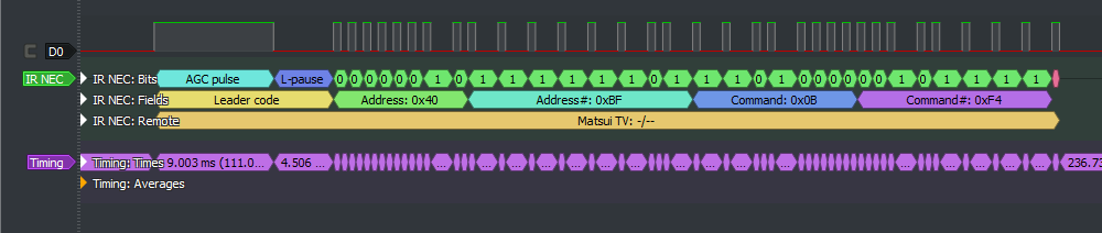
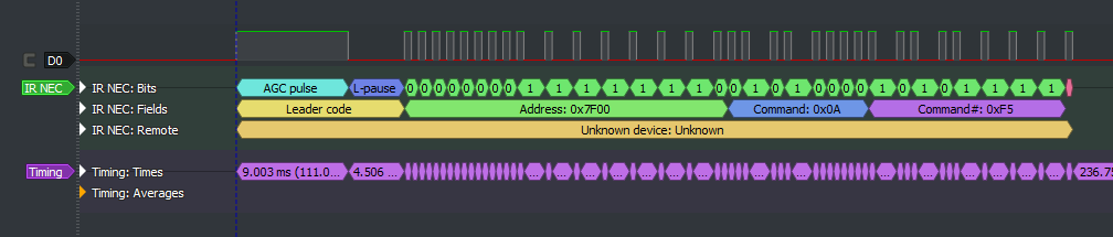
NEC encoding diagrams
Created with sigrok PulseView with IR_NEC decoder by DjordjeMandic.
8 bit address NEC code
 16 bit address NEC code
Quick comparison of 5 Arduino IR receiving libraries
Here you find an ESP8266/ESP32 version of IRremote with an impressive list of supported protocols.
This is a short comparison and may not be complete or correct.
I created this comparison matrix for myself in order to choose a small IR lib for my project and to have a quick overview, when to choose which library.
It is dated from 24.06.2022. If you have complains about the data or request for extensions, please send a PM or open a discussion.
| Subject | IRMP | IRLremote | IRLib2 mostly unmaintained |
IRremote | Minimal NEC | IRsmallDecoder |
|---|---|---|---|---|---|---|
| Number of protocols | 50 | Nec + Panasonic + Hash * | 12 + Hash * | 17 + PulseDistance + Hash * | NEC | NEC + RC5 + Sony + Samsung |
| Timing method receive | Timer2 or interrupt for pin 2 or 3 | Interrupt | Timer2 or interrupt for pin 2 or 3 | Timer2 | Interrupt | Interrupt |
| Timing method send | PWM and timing with Timer2 interrupts | Timer2 interrupts | Timer2 and blocking wait | PWM with Timer2 and/or blocking wait with delay Microseconds() |
% | % |
| Send pins | All | All | All ? | Timer dependent | % | % |
| Decode method | OnTheFly | OnTheFly | RAM | RAM | OnTheFly | OnTheFly |
| Encode method | OnTheFly | OnTheFly | OnTheFly | OnTheFly or RAM | % | % |
| Callback suppport | x | % | % | % | x | % |
| Repeat handling | Receive + Send (partially) | % | ? | Receive + Send | Receive | Receive |
| LED feedback | x | % | x | x | x | % |
| FLASH usage (simple NEC example with 5 prints) | 1820 (4300 for 15 main / 8000 for all 40 protocols) (+200 for callback) (+80 for interrupt at pin 2+3) |
1270 (1400 for pin 2+3) |
4830 | 1770 | 900 | ?1100? |
| RAM usage | 52 (73 / 100 for 15 (main) / 40 protocols) |
62 | 334 | 227 | 19 | 29 |
| Supported platforms | avr, megaavr, attiny, Digispark (Pro), esp8266, ESP32, STM32, SAMD 21, Apollo3 (plus arm and pic for non Arduino IDE) |
avr, esp8266 | avr, SAMD 21, SAMD 51 | avr, attiny, esp8266, esp32, SAM, SAMD | All platforms with attach Interrupt() |
All platforms with attach Interrupt() |
| Last library update | 6/2022 | 4/2018 | 3/2022 | 6/2022 | 6/2022 | 2/2022 |
| Remarks | Decodes 40 protocols concurrently. 39 Protocols to send. Work in progress. |
Only one protocol at a time. | Consists of 5 libraries. Project containing bugs - 45 issues, no reaction for at least one year. | Decoding and sending are easy to extend. Supports Pronto codes. |
Requires no timer. | Requires no timer. |
* The Hash protocol gives you a hash as code, which may be sufficient to distinguish your keys on the remote, but may not work with some protocols like Mitsubishi
Useful links
- List of public IR code databases
- LIRC database
- [IRMP list of IR protocols](https://www.mikrocontroller.net/articles/IRMP_-_english#IR_Protocols]
- IR Remote Control Theory and some protocols (upper right hamburger icon)
- Interpreting Decoded IR Signals (v2.45)
- "Recording long Infrared Remote control signals with Arduino"
- The original blog post of Ken Shirriff A Multi-Protocol Infrared Remote Library for the Arduino
- Vishay datasheet
License
Up to the version 2.7.0, the License is GPLv2. From the version 2.8.0, the license is the MIT license.
Copyright
Initially coded 2009 Ken Shirriff http://www.righto.com
Copyright (c) 2016-2017 Rafi Khan
Copyright (c) 2020-2022 Armin Joachimsmeyer